PEB drawings are technical documents used to design, fabricate, and construct pre-engineered buildings. If they seem difficult to understand, focus on three key elements: structural layouts, member details, and connection drawings. These drawings act as a guide for engineers, fabricators, and contractors, ensuring that all steel components fit together accurately during erection.
With the growing demand for pre-engineered building design projects in India, understanding PEB drawings has become increasingly important. Whether you are reviewing shop drawings or coordinating fabrication activities, this guide will help simplify the process and improve project efficiency.
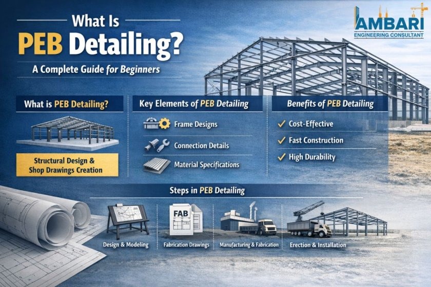
PEB drawings are engineering drawings that provide all the information required to design, fabricate, and assemble a pre-engineered building.
They typically include:
These drawings help minimize manufacturing and construction errors while ensuring compliance with project requirements.
Without accurate drawings, even a well-designed steel structure can face delays, rework, and costly mistakes.
Professional PEB design and detailing services play a major role in producing accurate drawings that improve project efficiency from design through execution.
These drawings show the overall layout, dimensions, elevations, and structural framing arrangement of the building.
Shop drawings provide detailed fabrication information for each steel member, helping manufacturers produce components accurately.
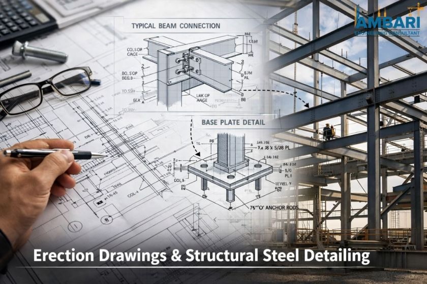
These drawings illustrate how structural elements are connected using bolts, welds, plates, and other connection components.
Erection drawings guide site teams during the installation and assembly of structural components.
| Drawing Type | Purpose |
|---|---|
| GA Drawing | Overall building layout |
| Shop Drawing | Fabrication details |
| Connection Drawing | Joint and connection details |
| Erection Drawing | Installation guidance |
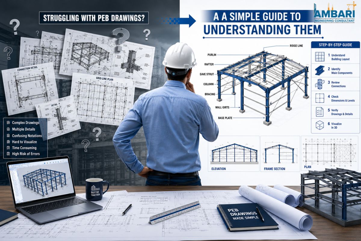
Follow a systematic approach to understand PEB drawings effectively.
Start by understanding the symbols, abbreviations, notes, and drawing references used throughout the document.
Review the overall building length, width, height, bay spacing, and other critical dimensions.
Locate major structural components such as columns, rafters, purlins, girts, and bracing systems.
Pay close attention to bolt sizes, weld specifications, connection plates, and assembly requirements.
Verify steel grades, sizes, and fabrication specifications.
Furthermore, professional structural steel detailing services often come with detailed annotations that make it easier for the manufacturing and building teams.
PEB drawings can sometimes be difficult to interpret, especially for professionals who are new to steel building projects. Understanding common challenges and their solutions can help improve project coordination and execution.
Solution: Use the drawing legend, engineering notes, and reference sections to understand symbols, abbreviations, and notations quickly.
Solution: Focus on enlarged connection details, section views, and fabrication notes to clearly understand how structural members are joined.
Solution: Cross-reference General Arrangement (GA), shop, connection, and erection drawings to maintain consistency throughout the project.
Solution: Work with experienced teams providing PEB detailing services to ensure drawing clarity, accuracy, and proper documentation.
Well-prepared PEB drawings play a vital role throughout the project lifecycle and contribute significantly to overall project success.
Detailed engineering coordination and accurate drawing preparation help create documentation that is practical, reliable, and suitable for fabrication and construction activities.
A manufacturing facility project required the installation of multiple steel frames within a tight construction schedule.
During the initial stages, the project team experienced challenges due to poor coordination between fabrication and on-site installation activities. To address these issues, detailed shop drawings and erection drawings were introduced to improve communication and workflow management.
As a result:
This example demonstrates how accurate and well-coordinated PEB drawings contribute directly to project success and construction efficiency.
Modern steel construction projects demand precision, speed, and strict compliance with industry standards.
Professional detailing teams help organizations by:
Specialized detailing expertise helps ensure smoother construction processes, better communication among project stakeholders, and improved project outcomes.
For pre-engineered building projects in India, many organizations rely on professional detailing teams to achieve higher levels of quality, accuracy, and execution efficiency.
PEB drawings form the foundation of every successful steel building project. Although the symbols, layouts, and technical information may initially appear complex, understanding the different drawing types and their purpose makes them much easier to interpret.
Whether you are an engineer, contractor, fabricator, or project owner, taking the time to understand PEB drawings can improve project coordination, reduce costly mistakes, and enhance overall construction efficiency.
Professional engineering and detailing support further ensures smooth project execution from design and fabrication through erection and final completion.
A PEB drawing is a technical drawing that illustrates the design, fabrication, and erection requirements of a pre-engineered building.
PEB drawings are used by structural engineers, detailers, fabricators, contractors, and project managers throughout the construction process.
Shop drawings provide fabrication-level details that ensure accurate manufacturing of steel components and reduce production errors.
PEB detailing typically includes structural layouts, connection details, member specifications, fabrication drawings, material information, and erection plans.
Accurate PEB drawings help minimize fabrication errors, reduce rework, improve coordination, optimize material usage, and accelerate construction schedules.